Sillybutts continues to be one of the most prolific designers in the hobby. He has experimented with just about every springer priming action, but he had yet to design his own take on the standard pump-action blaster style—that is, until recently.
Enter Alchemist. This 3D-printed, mag-fed, short dart pump-action springer is the culmination of the hobby's latest and greatest quality-of-life features, including a rock-solid tensioned body, buttery smooth bearing-assisted prime, detent prime hold, and more. Already, this is becoming a favorite of super-stock, ultra-stock, and competitive foam-flingers, including yours truly.
Because of the dovetails, pins, and 4-40 screws making the assembly of this blaster not much more complicated than a large Lego set, we decided it would still be best to condense and improve upon Sillybutts' original build tutorial in our "crystal clear" style. Let’s get to it!
Kit, Tools & Supplies Needed
With that out of the way, let’s talk about what you need to complete this build. First, you will need one of the kits we sell on the shop. For DIYers, we offer both a Hardware Kit—where you print the 3D parts yourself—and a 3DParts + Hardware Kit—which includes everything you need to build this blaster yourself. If you’d like to skip the tutorial and get a ready-to-fire blaster shipped to you, you can opt to purchase the Alchemist fully assembled.
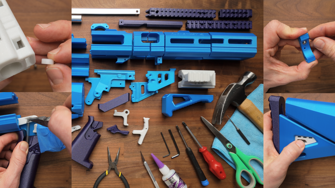
As far as tools, you’re going to need:
- Pliers
- X-Acto hobby knife
- Cyanoacrylate “super” glue
- M2.5 hex key
- M4 hex key
- #1 Phillips screwdriver
- #2 Phillips screwdriver
- Scissors
Optionally, if you’re printing your own parts, you may need a pin punch and hammer or a 3/16-inch drill bit to help set the takedown pin at the rear of the blaster. If you don’t own a pin punch, a hex key or old stock flywheel motor will suffice.
Assembling the Tensioner
The tensioner is one of the coolest parts of this blaster that tightens the whole blaster and makes it feel rock-solid. To assemble, take a 10-32 nut and secure it into the tensioner block with two 4-40 screws using a #1 Philips screwdriver. We find it helps to hold the nut in place by pre-installing the M4 bolt and washer into the nut from the flat side before installing the 4-40 screws. You will need to take the M4 bolt out later, but it does keep it nice and contained.

Next, take the completed tensioner block and attach them to the two longest flat bars with two 4-40 screws on either side. The M4 bolt should face out the end, where the front muzzle will be, and not toward the center of the bars. If you have any marks on your bars from our production process, ensure the smoothest side is facing inward. Unlike other 3D-printed springers where smooth bars are merely cosmetic, two of the POM bearings in the priming block ride on the inside of these flat bars, and any imperfections will transfer into the feel of the prime later.
Assembling the Plunger
Take the plunger rod, body, and head, and combine them with two M3 x 16mm screws through the face of the plunger head. Each of these parts are keyed to fit only one way. Next, take the M3 x 30mm screw and thread it through the side of the plunger body. Note that all three screws will be under immense stress during use, so make sure that they are fully tightened. After that, you can install one of the 123 O-rings along the groove of the plunger head.

Assembling the priming block
Starting with the inside of the priming block, use pliers or tweezers to place four of the bearings in their slots in the priming block. While holding the bearing in with your finger, drive the corresponding M3 x 12mm screw through the priming block and into the bearing, making sure that the bearings move freely after they are installed.
Next, slide the barrel through, place the fifth bearing in the slot at the top of the priming block, and screw it into one of the three stepped holes. The placement of this bearing depends on your 3D printer's tolerances, but you want the bearing to fit snugly against the barrel. After installing, make sure all the installed bearings glide along the barrel smoothly.

Next, install the last two POM bearings on the side of the priming block. These holes are also stepped and will depend on fit and tolerances. For now, you can pre-install them into the loosest fitting arrangement, so they are out of the way until tuning later.
Assembling the Ram
Start by stretching one of the 012 O-rings over the back of the ram core and run it through the first of the 3D parts. Then sandwich that same O-ring into place with the second 3D part and secure them together with four 4-40 screws through the back. Place one more 123 O-ring into its corresponding groove.

Next, take four more 4-40 screws, and screw them into the countersunk holes along the side to further secure the ram core in place. Tighten these screws evenly in diagonal pairs, and make sure to not over-tighten them.
Next, take two 012 O-rings and install them onto the ram core in their corresponding groove. Take the rubber bumper and stick it on the back of the ram assembly. If, for whatever reason, this falls off, you can refresh the adhesive with a bit of glue.
Now, attach the priming bars to the ram assembly with four more 4-40 screws.
Assembling the Magwell
Next, take the printed piece that holds the ball detent in place. This is a really nice quality-of-life feature that Silly added. It lightly holds your prime in place so it doesn’t come loose when holding the blaster vertically. Depending on your prints, you'll want to clean up this little hole with a hobby knife and install the detent with a little bit of CA glue to make sure that it doesn't ever come out later.
Place one of the small pins on one side of the magwell. Slide the mag release onto that pin and sandwich it with the other magwell piece, lining up the pin with its corresponding hole. While holding this part together, hook the magwell flare part and rock it into place, securing all four parts with two 4-40 screws through the bottom of the magwell flare part. The mag release should still move freely.
Next, tie a knot on one end of the elastic and thread the untied end through the holes and around the outside of the mag release. Holding the elastic taut, tie another knot as close to the magwell as possible. If the knot is too loose, you may need to double-knot or fuse the end with a lighter or soldering iron.
Check that a mag goes in, the mag release locks and holds onto the mag, and the mag releases easily. Then, take a pair of scissors or your hobby knife and cut off the access, leaving a little extra so that the knot doesn’t come undone by itself (if you choose to single-knot it).

Secure the printed part with the installed detent into the rear upper magwell piece with two 4-40 screws and the assembled rear upper magwell to the lower magwell assembly with two more 4-40 screws. Then, with three more small pins, add the front half of the upper magwell to the assembly. You may optionally secure this with Rail B, but we have opted to install that later.
This is another good time to insert a magazine and ensure nothing impedes it from seating in its proper place and releasing when engaging the mag release.
Assembling the Front Half
Take the part of the front half of the blaster that says “Alchemist,” and install a 016 O-ring in the groove. You can work it in place with your finger or a tool.
Next, take the two front muzzle pieces and combine them with four 4-40 screws through the front. Optionally, you may install and trap a square nut with a 4-40 screw in one of these pieces for a more permanent barrel installation later. If you prefer quick barrel swaps, you can skip this square nut and screw altogether.
Assembling the Grip
Combine the grip, the left grip plate, and the trigger guard with two 4-40 screws. Seat the trigger spring between the indents on the trigger and grip and loosely set the whole assembly with a nylon spacer. This spring is optional, as the sear also has its own spring. The only purpose of this spring is to make the trigger pull feel lighter. If you encounter problems with the blaster catching, you may opt to remove this secondary spring entirely.

Install two more 4-40 screws: one in the hole midway down the grip and the other into the end of the sear. These two screws should be installed partway so that they can be used to install the primary trigger spring. In the case of the sear, you want to ensure the screw is past flush with the majority of the sear while also not overly tight that you cannot install the trigger spring.
Assembling the Skeggox Stock
First, take the medium of the three 10-32 screws and drive this into the top of the butt plate to reinforce the part. Slide the butt plate into the other part of the stock using the dovetail until it’s flush at the bottom, and secure the two parts with two 4-40 screws into the back of the butt plate.

Take the longest of the three 10-32 bolts and drive it through the two rear blaster parts the stock attaches to. Secure these two parts even further with two 4-40 screws from the front. You can now combine the completed stock receiver and the stock itself with the printed Picatinny Key part and a 4-40 screw through the bottom of the stock.
Finally, take your sear and a nylon spacer and install them in between the appropriate indents, securing them together with two 4-40 screws.
Assembling the Grip + Trigger
What follows is probably the trickiest part of the whole build. While securing the completed trigger assembly, insert the dovetail of the left grip plate into its corresponding hole and loop the primary trigger spring to the partially installed screws in the grip and on the sear. While filming this video, we found it best to use painter's or masking tape to hold down the trigger assembly while connecting the sear.

Once installed, the tension of this spring may cause the left grip plate to fall out of its hole. Don’t panic! We needed to do this anyway! Carefully remove the tape on the left side of the grip interior and install the remaining right grip plate with two 4-40 screws. Be careful not to pull the grip too far away from the rest of the blaster assembly because you'll overstretch the trigger spring. Now, install the grip back in place using its dovetails.
Installing the Plunger Tube
Next, take the plunger tube and apply a bead of lubricant around the inside. Then, spread the lubricant around using the assembled plunger. Insert the plunger tube into its 3D part, add the rear rail, and install the combined pieces into the rear of the blaster, aligning all of the dovetails as you go. Eventually, it'll all be together, and you can put two screws through the top of the Picatinny rail.

Lastly, secure the front of the grip plates to the plunger assembly with two 4-40 screws: one on either side. The rear of the blaster should now be fully assembled, and you should be able to see the trigger and sear activate in tandem with each other.
Assembling the Front Half
If you haven't already, take the tensioner assembly and remove the M4 bolt. Slide the front muzzle piece down onto the tensioner assembly and reinstall the M4 bolt from the outside. Do not fully tighten the M4 bolt yet; you need it loose to complete the rest of the assembly.
Place two small pins into the magwell assembly and “Alchemist” part, lining up the holes and dovetails. Then take rail B and combine all parts using four 4-40 screws through the top. It's worth noting that there are custom supports in the dovetail on the underside of the rail. If you are printing your own parts or if we missed support material when prepping the parts, it’s easy enough to break off those supports using a pair of pliers.
Next, take the priming block assembly and the ram assembly and combine the two with the magwell assembly sandwiched in between using four 10-30 nuts and four 10-32 screws with lock washers on either side of the flat bars.

Finally, take the two front assemblies and slide them together, sandwiching Rail A onto the dovetails and securing it using two 4-40 screws through the top. Install the barrel into the front assembly and check the fit of the two bearings running against the inside of the flat bars. Depending on print tolerances and hardware fit, you may need to readjust the location of these two bearings. Note that the bearings can be parallel to each other, and they can be one space away, but they shouldn’t be two spaces away, or it can harm your prime’s alignment.
Installing the Plunger
Next, take the plunger and spring, minding any excess lubricant, and install them into the rear half of the blaster. Note that there are two arrows: one on the plunger head and one on the front of the rear assembly. Both arrows need to be facing down in the same direction. You may need to jiggle them for the plunger rod to fall into its proper place.

Final Assembly
Put the two halves of the blaster together, adding a few drops of lubricant onto the O-rings on the ram. After all the parts are together, press down on the M4 bolt to ensure the long flat bars are fully seated in the back of the blaster. If the holes aren’t lining up, you may need to loosen the M4 bolt even more.
Insert the Takedown pin into its hole at the rear of the blaster. If you find that this hole is too tight, you can ream it out with a hobby knife or a 3/16-inch drill bit to ensure that it can go all the way through the blaster's body. Reinsert and tighten the M4 bolt to compress the parts together.

Reinstall the barrel, adding a little twist to make sure it’s seated against that O-ring. Then, roll an 016 O-ring onto the barrel, sandwiching it between the muzzle part and the collet to secure the barrel. Optionally, you can also secure the barrel using the set screw accessible through the top of Rail A, making sure only to go finger-tight because it is a metal screw going into a metal barrel.
Installing the Angled Foregrip and Silly SCAR
Slide on the grip part from the front and drop the Picatinny key through the hole, setting it in place with a 4-40 screw through the bottom of the grip.

If you get the 3D Parts + Hardware Kit from us, you’ll also receive a complimentary Silly SCAR for a boost in accuracy and compliance. Similarly to the barrel collet, but in reverse, install the collet onto the barrel, roll an 016 O-ring onto the barrel, and sandwich the O-ring with the collet and the body of the PCAR while putting some positive pressure on the PCAR itself.
• • •
Here we have a completed Alchemist by Sillybutts. You can now test the blaster and admire that smoooooth prime.

A special thank you to Sillybutts for creating his own tutorial. It helped us a ton with our video tutorial, this blog post, and building out our assembly process at the warehouse.
Let us know if you have any questions about your blaster or if you have trouble with assembly! As always, hit us up by email: orders@outofdarts.com. We're always here to help. – Luke Goodman